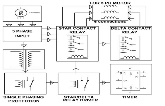
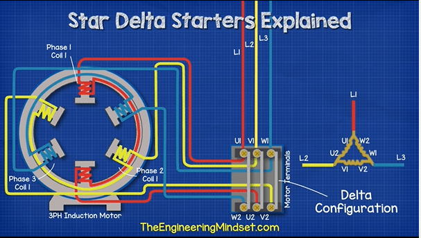
Star delta connection diagram and working principle. For star delta staterthe motor connection must have 6 cables from control panel and 6 terminals at induction motor u1u2v1v2w1w3to wiring the motor connection for star delta starterthe important thing that we must fully understand is about the basic of star delta magic triangle.
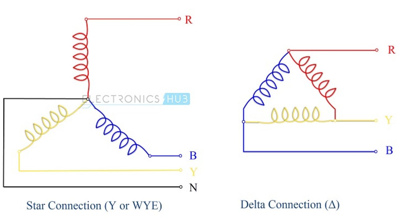
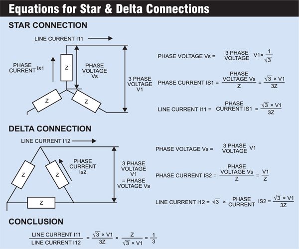
Star connection y delta connection d in star connection the starting or finishing ends similar ends of three coils are connected together to form the neutral point.
You can find out more Diagram below
Diagram of star delta connection. Hence in delta connection line voltage is equal to phase voltage. There is minor correction is require to change printed in boxes sequence of 3 phase wires from w2 v2 u2 to w2 u2 v2 to get delta connection properly. A common wire is taken out from the neutral point which is called neutral.
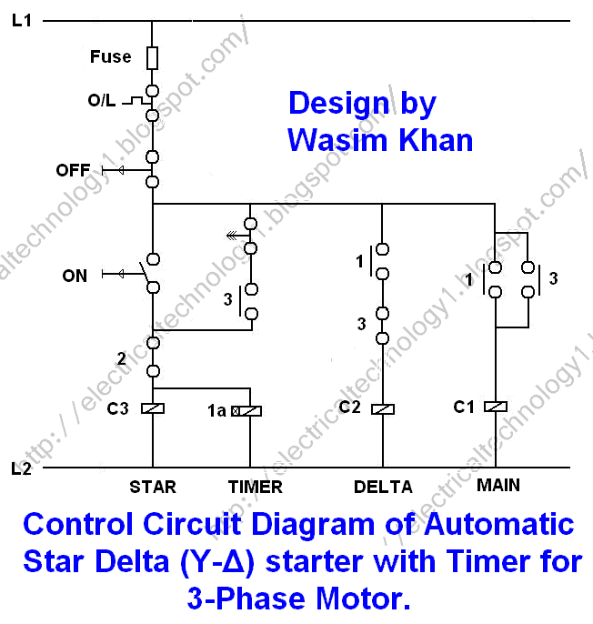
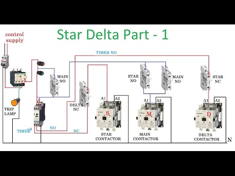
In other words the end of each coil is connected with the starting point of another coil and three wires are taken out from the coil joints. In star delta starter current peak and mechanical load on changeover from star delta. So this time i want share my simple star delta circuit diagram completed with power and control line circuiti hope it can be as basic reference for all electrician about star delta starter diagram.
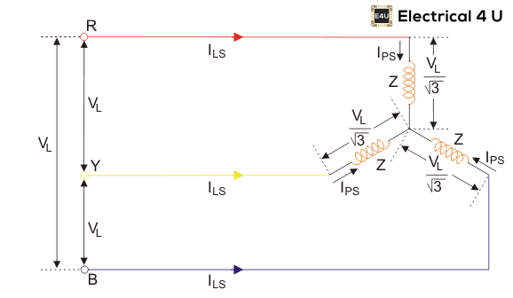
Star delta starter can be used only for low to high power three phase induction motors. The phasor diagram is shown below. In delta connection the opposite ends of three coils are connected together.
It has reduced starting current and torque. The 6 connection cables are needed for motor terminal box. A dual starter connects the motor terminals directly to the power supply.
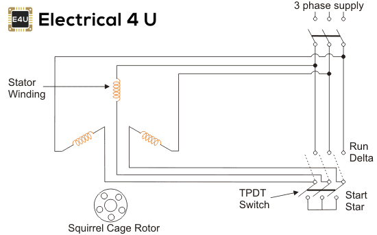
Star delta starter is a common used in domestic and industry sector to drive variant application such as chiller water pumpmachineryair compressor and many more equipment. Applications of star delta starter. A star delta starter wiring diagram 3 phase motor.
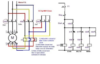
Star delta starter diagram with connection of 3 phase motor and control circuit wiring. Consequently high starting current flows through the motor. Star delta motor connection.
In the diagram of power circuit of star delta starter u2 and v2 of 3 phase motor should be connect to 4 and 6 respectively instead of u2 and v2 are connected to 6 and 4 of delta contector km2. As in the balanced system the three phase current i 12 i 23 and i 31 are equal in magnitude but are displaced from one another by 120 degrees electrical. Relation between phase current and line current in delta connection.
Hence the motor is subjected to the full voltage of the power supply. Electrical online 4u a platform to learn electrical wiring single phase 3 phase wiring controlling hvac electrical installation electrical diagrams. This type of starting is suitable for small motors below 5 hp 375 kw.


0 comments:
Post a Comment