Both line and wiring diagrams are a language of pictures. It is not difficult to learn the basic symbols.
Protecting small ac and dc motors rated at 1 hp or less where.

You can find out more Diagram below
Ac motor starter diagram. Wiring diagrams do not show the operating mechanism since it is not electrically controlled. The input current to the started equals its output current. Your motor starter may use wiring which is internal to the starter wiring which is different than the diagrams etc.
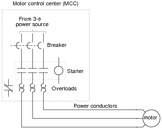
They can be used as a guide when wiring the controller. A motor starter is a combination of devices used to start run and stop an ac induction motor based on commands from an operator or a controller. Also explain the operation of this motor control circuit.
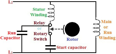
Please refer to the manufacturers literature if in doubt. Wondering how a capacitor can be used to start a single phase motor. The soft starter is similar to a primary resistance or primary reactant starter in that it is in series with the supply to the motor.
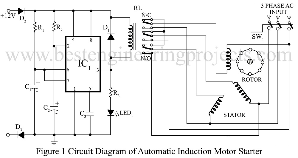
Based on your observations of these two diagrams explain how electromechanical relays are represented differently between ladder and schematic diagrams. An automatic starter operates in a similar fashion except that automatic relays short out sections of the starter resistance either by a time sequence or when the armature current drops to a selected value. A soft starter is a type of reduced voltage starter for ac induction motors.
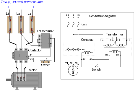
Four point manual dc motor starter circuit diagram. Ceiling fan wiring diagram with capacitor connection ceiling fan has a capacitor start motor in its inside ac single phase capacitor start motor has two winding one is starting winding and another is wiring diagram electric motor reverse new wiring diagram for reversing motor starter save capacitor start. Figure 1 is a typical wiring diagram for a three phase magnetic motor starter.
Wiring diagrams ww introduction. In north america an induction motor will typically operate at 230v or 460v 3 phase 60 hz and has a control voltage of 115 vac or 24 vdc. Star delta y d 3 phase motor starting method by automatic star delta starter with timer.
Click here to view a capacitor start motor circuit diagram for starting a single phase motor. Three phase motor power control wiring diagrams three phase motor connection schematic power and control wiring installation diagrams. They show the relative location of the components.
Learn how a capacitor start induction run motor is capable of producing twice as much torque of a split phase motor. Figure 4 shows the automatic dc starter circuit diagram. These motor starters consist of an on off snap switch combined with.
Also read about the speed torque characteristics of these motors along with its different types. Interpret this ac motor control circuit diagram explaining the meaning of each symbol. If you are not sure of how to make the connections on your equipment hire an electrician.


0 comments:
Post a Comment